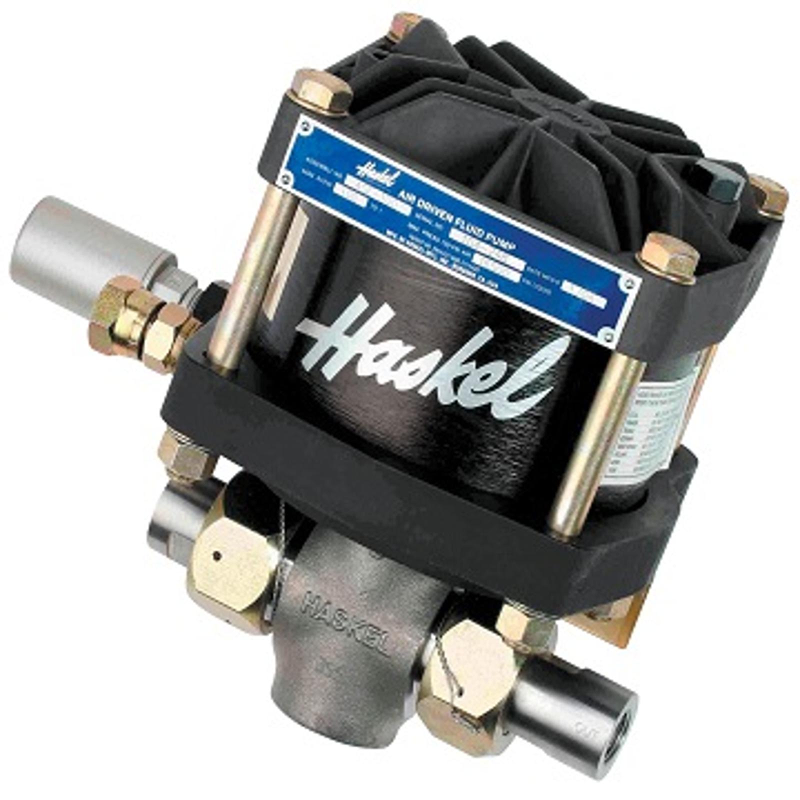
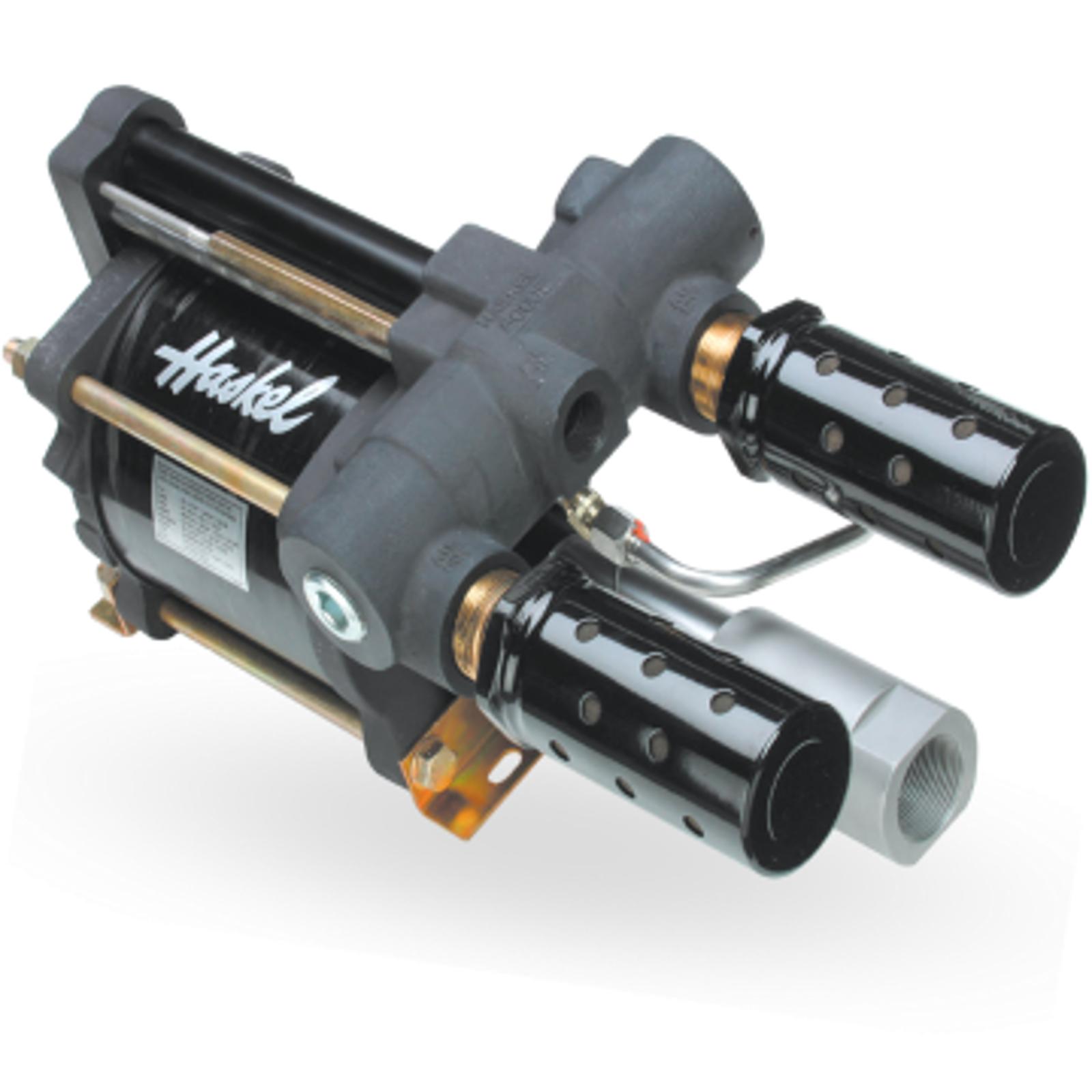
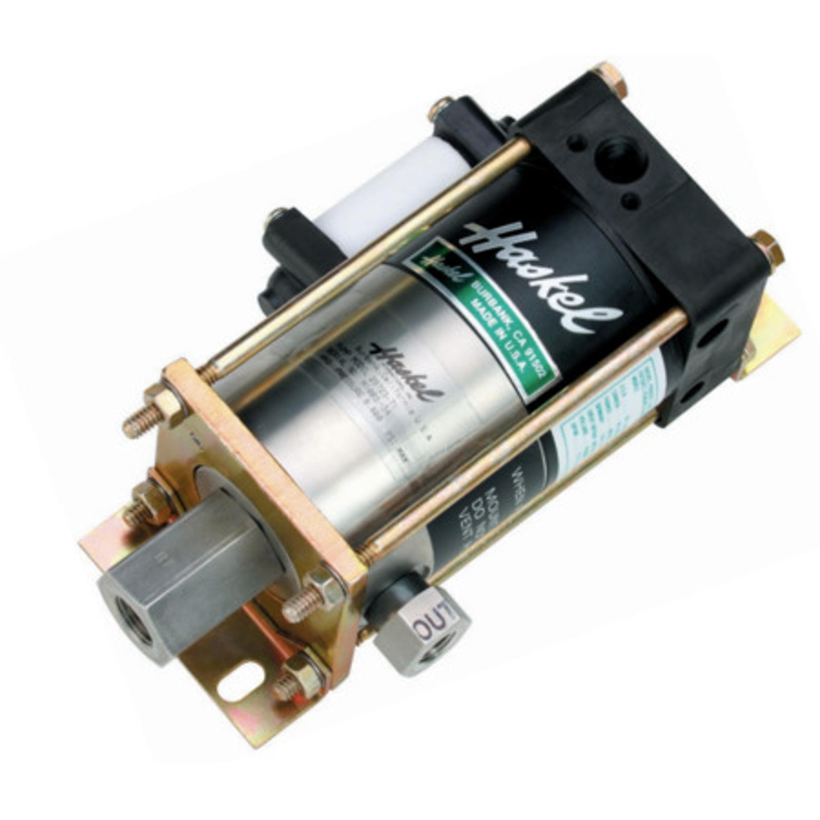
{{recommendedBannerText}}
{{currentRegion}} {{countryFromLanguage}} {{languageshort}}
A Haskel pneumatic pump’s robust design will efficiently convert compressed air into hydraulic power, satisfying any application need for pressurizing up a component and holding it at a set pressure for any sustained period of time.
Backed by a global network of high-pressure expertise, service and support, our pneumatic pumps are consistently recognized as the most reliable in the industry.
The pumps automatically reciprocate on a differential piston principle. A large
piston driven by relatively low pressure drive acts directly upon a smaller hydraulic piston.
The nominal ratio between piston sizes is indicated in the model coding and approximates to the maximum working pressure. The actual ratio is about 15% above nominal so that the pump continues to cycle when drive pressure
equals nominal ratio. Initially, the pump will cycle at maximum speed acting as a transfer pump to pressurize downstream.
It will cycle at a slower rate as the fluid meets resistance until it stalls at maximum output pressure. When a pressure drop downstream occurs, it will recycle as necessary in an
effort to maintain maximum pressure.
Stall pressure is achieved when the outlet pressure rises and offers more resistance to the reciprocating differential piston assembly. The piston assembly then stalls when the forces
balance, e.g. when drive pressure x drive piston area equals outlet (stall) pressure
x driven hydraulic plunger area. The pump design is sensitive to very small pressure drops due to the low frictional resistance of the large diameter drive
piston and hydraulic piston seals.
1. Drive Section
The piston, complete with “O” ring seal, operates in an epoxy filled,fiberglass wound barrel, the diameter of which is constant throughout a given series of pumps. Drive media forces the piston down on the compression stroke and raises it on the suction stroke (M series have a spring return). The piston is pre-lubricated during assembly and therefore no air line lubricator is necessary.
2. Hydraulic Section/Check Valves
The drive piston is linked and connected to the hydraulic plunger/piston in the hydraulic section. Outlet flow and pressure are determined by the area of the hydraulic piston head, its nominal ratio with the drive piston head, and drive pressure. On the down stroke, liquid in the hydraulic section is forced under compression through the outlet check valve. Fresh liquid is induced via the inlet check valve on the return stroke. These check valves control the flow of liquid through the hydraulic section. They are spring-loaded and have a very low cracking pressure, allowing maximum opening on the induction stroke. The pressure of hydraulic fluid on the down stroke closes the inlet check valve and acts against the spring to open the outlet check valve.
3. Drive Cycling Valve
This is a pilot-operated, unbalanced, lightweight spool, which directs drive pressure, first to the top of the drive piston, and then to the underside to reciprocate the piston (cycle). It actuates via pilot valves at the top and the bottom of the stroke, which causes the unbalanced spool to shift and reciprocate the piston.
4. Hydraulic Seal/Check Valves
This is one of the few wear parts. Its function is to allow the hydraulic piston to reciprocate without passing fluid into the drive section. The liquid, its pressure and its temperature determine seal specification. A distance piece can be incorporated between drive and hydraulic sections for complete contamination-free operation on most Haskel pumps.
Proven to be safe, robust, reliable, compact, and easy to maintain, Haskel pneumatic-driven liquid pumps provide a number of operational benefits:
Efficiently convert compressed air into hydraulic power, satisfying any application need for pressurizing up a component and holding it at a set pressure for any sustained period of time. Other applications include: